
by William Waites
07 Sep 2012
The Arduino Voltmeter


When testing the Long Link to Eigg, we ran into a problem with the solar powered mast at Coille Mhialairigh. Whenever we put any particular load on the network there, the switch at the mast would reboot – even if the traffic itself didn’t touch the switch. The suspicion is that the extra load on the power supply causes the voltage to drop outwith the tolerance of the little netgear switch.
Testing this hypothesis is not easy, however. It might involve a lot of sitting in the cold on top of a hill with a voltmeter while the problem is reproduced. Much better to try to arrange to be able to do it from the comfort of the house, by the warm fire.
Recently at the EMF Camp we were given badges that contained little boards with Arduino micro-controllers on-board. These are fantastically flexible tiny computers, intended primarily for artists making electronic scuptures, and for use in the classroom to help teach basic electronics, and of course for hobbyists who put them to all sorts of uses.
In this case the task is pretty simple – measure the power supply voltage which, in practice will be the same supply that powers the Arduino board itself. This is done by using an analogue input pin on the board. It has six, but we only need one. These pins allow to read a voltage in the 0-5V range, which is turned into a number between 0 and 1023.
The power supply cannot be directly plugged into the analogue input because it runs at 12V and would burn out the pin. So a simple voltage divider circuit is used:
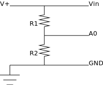
The resistors, R1 and R2 are chosen so that they are in a ratio of more or less 3:1. This means that, roughly the input can range from 0-20V and by tapping in between the resistors it will have been reduced by ¾ and what is measured on the A0 pin will be in the correct range.
The actual voltage is reconstructed like so:
[ V^{+} = A_0 \frac{5}{1024} \frac{R_1 + R_2}{R_2} ]
The chosen values are, \(R_1 = 680 k\Omega\), \(R_2 = 220 k\Omega\). This corresponds at 12V to a current of \(13 \mu A\) (cf. Ohm’s Law) – meaning measuring the voltage won’t appreciably drain the batteries. Of course this needs to be added to the couple of hundred milliamperes that the board itself will draw.
To make it convenient to retrieve the readings, the Arduino Ethernet Shield is used, together with the Webduino library. The entire program is a tiny 162 lines of code, including comments and blank lines.
It does two things:
- Interrupt every second and take a new voltage reading, add the reading to a circular buffer.
- Upon receiving an HTTP GET request, serve up the contents of the buffer as a JSON document.
The reason for the circular buffer is so that the readings can be stored while the faulty switch is rebooting and read out afterwards without losing any data.
Now to head back up North and install it and see what we find!
